Floating wind has moved from “interesting demo” to an operating part of the offshore wind mix, mainly because it unlocks deeper waters where fixed-bottom foundations are impractical. As of late 2025, global floating wind installations were reported at 277 MW, up from 245 MW a year earlier, which is still small compared with bottom-fixed offshore wind but big enough to prove what works—and what fails—at sea. In 2026, the engineering discussion is less about whether floating wind can run, and more about how to keep moorings, anchors and dynamic cables reliable for decades while controlling offshore servicing costs.
Underwater Anchors and Mooring Systems: What Holds a Floating Turbine in Place
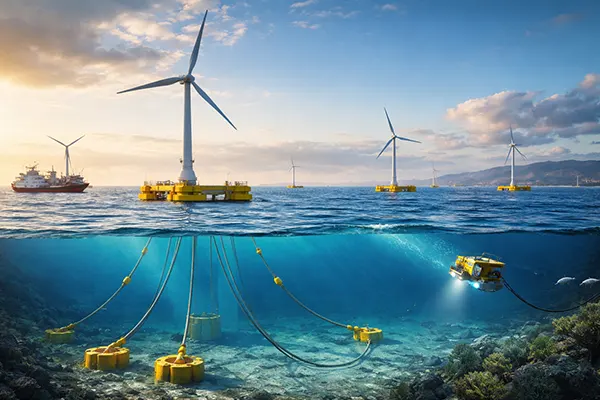
Anchoring starts with the seabed, not the turbine. Before an anchor type is chosen, developers run geophysical surveys (bathymetry, side-scan sonar, sub-bottom profiling) and geotechnical campaigns (CPTs, boreholes, lab testing) to understand soil strength, layering and cyclic behaviour. That data decides whether suction piles, driven piles, drag-embedded anchors, or gravity-based solutions make sense, and it also shapes mooring geometry—catenary systems that lie partly on the seabed, taut-leg systems with higher vertical loads, or hybrids. The aim is simple: keep offsets within limits, keep line tensions predictable, and avoid fatigue hotspots at fairleads and terminations.
Suction piles are a common choice for many floating wind concepts because they can deliver high holding capacity with relatively controlled installation. A large steel caisson is set on the seabed and “sucked” into place by pumping water out, which creates a pressure differential. They are sensitive to soil permeability and installation procedures, but they offer good performance in soft clays and some sands when designed correctly. Drag anchors can look attractive on paper because they can be installed quickly, yet their capacity depends heavily on soil type and embedment quality—and they generally require more seabed “real estate” for line lay-down and movement during installation.
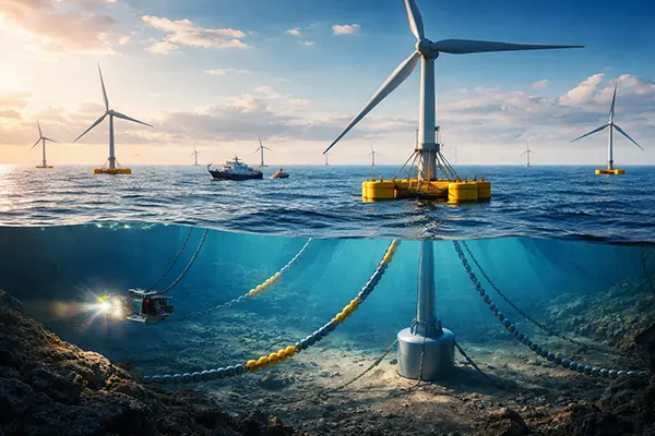
Mooring lines are usually a mix of chain, wire and synthetic rope (often polyester for deep water due to lower weight). The tricky part is not strength in a static sense; it is fatigue under repeated wave and wind loading, plus corrosion and wear at touch-down points. Modern designs increasingly include load monitoring and digital condition tracking, because a slow drift in stiffness, corrosion loss or connector wear can quietly turn into an emergency tow. In 2026, another major theme is shared infrastructure: shared anchors or shared mooring corridors can cut costs, but they demand tight rules for inspection access, repair logistics and responsibilities when something goes wrong.
Installation, Inspection and Life-Cycle Risks Below the Waterline
Anchor installation is a marine operation with a narrow tolerance for mistakes. For suction piles, operators need reliable pumps, stable verticality control, and verification of final embedment. For driven piles, they need accurate positioning, hammer energy control and noise mitigation planning where required. Every method requires as-built documentation, because later inspections depend on knowing the exact geometry and connector locations. If your drawings do not match reality, the offshore crew loses time—and time offshore is where budgets burn fastest.
Inspection and maintenance below the waterline is usually done with ROVs, sometimes supported by AUV surveys for broader coverage. Visual checks look for coating breakdown, chain wear, seabed scour near anchors, and deformation at connectors. Measurement tools add thickness gauging, cathodic protection readings and tension checks. The industry has learned—sometimes the hard way—that small issues compound: a worn chain link increases local stress, which accelerates fatigue cracking; a slightly shifted touch-down point changes bending cycles; a corroded shackle pin becomes the weak link in the system.
Life-cycle risk management comes down to three habits: conservative design allowances, realistic inspection intervals, and a repair plan that assumes bad weather. A repair plan is not a paragraph in a report; it is a pre-arranged set of vessels, spare components, tooling and procedures that can be mobilised quickly. The most credible projects treat moorings and anchors like critical assets, not background hardware. If you can’t confidently answer “how would we replace this connector in winter conditions?”, you don’t really have an operations plan.
Subsea Cables in Floating Wind: Dynamic Sections, Protection and Failure Modes
The electrical connection is where floating wind differs sharply from bottom-fixed wind. With a moving floater, the cable needs a dynamic section that can handle continuous motion while still protecting the conductors, insulation and armour from fatigue. In practice, many systems use a “lazy-wave” shape in the water column, created with buoyancy modules so the cable bends in a controlled way rather than at one sharp point. This reduces curvature and fatigue near the hang-off, but it also increases complexity: more components, more interfaces, more installation steps, and more things to inspect.
Cable design choices are not purely electrical; they are mechanical and operational. Array cables and export links must cope with cyclic bending, tension variations, and occasional extreme events. Engineers focus on bend stiffeners, hang-off clamps, armour layer design, and how to avoid abrasion where the cable might touch seabed or structure. Protection usually includes external sheathing, bend restrictors, and careful routing. In deeper water, the weight and dynamics of the cable become dominant drivers, which is why buoyancy and configuration optimisation has turned into a specialised discipline.
In 2026, cable reliability is also a finance topic. Insurers and lenders scrutinise dynamic cables because cable faults have historically produced large claims in offshore wind. Operators are increasingly using monitoring—temperature, partial discharge indicators, tension and motion sensors—to catch early warnings. The best outcome is not a heroic repair; it is preventing a fault from becoming a full outage by identifying abnormal behaviour early and scheduling an intervention during a workable weather window.
Testing, Monitoring and Repair Strategy for Dynamic Cables
Testing begins before installation. Cable systems go through factory acceptance testing, type testing for dynamic performance where applicable, and rigorous checks of terminations and joints. Offshore, the critical moment is the hang-off and first energisation, because that is when installation damage can reveal itself. Operators that treat this phase as routine often regret it later. A structured commissioning plan with clear acceptance criteria is a quiet cost-saver, because it reduces the chance of latent defects.
Monitoring is becoming more normal rather than experimental. Motion and tension data helps confirm that real behaviour matches simulation assumptions, and it can highlight shifts caused by mooring retensioning, seabed changes or component degradation. Electrical monitoring—such as insulation condition indicators—can identify trends before a trip event. These data streams only matter if someone is responsible for acting on them, so mature teams build clear thresholds and escalation routes, not just dashboards.
Repairs are difficult because the problem is often in a dynamic segment that is not easy to lift and re-terminate at sea. Some projects plan for in-situ repair using specialist vessels, while others treat tow-to-port as the main route for major electrical work. Each approach has trade-offs. Offshore repairs can be faster if weather cooperates, but mobilisation is expensive and uncertain. Tow-to-port reduces offshore complexity, yet it demands connectors and moorings designed for disconnection, plus port capacity, cranage and a safe re-connection procedure.
Service and Maintenance: How Floating Wind Is Kept Running Offshore
Operations and maintenance for floating wind is a blend of traditional offshore wind practice and offshore oil-and-gas style marine logistics. Routine tasks—inspections, minor mechanical work, blade checks—often use service operation vessels (SOVs) or crew transfer vessels (CTVs), depending on distance to port and sea conditions. In harsher regions, technicians may rely on walk-to-work gangways from SOVs to reduce transfer risk. Remote monitoring and condition-based maintenance are not buzzwords here; they are the difference between planned interventions and costly, weather-driven outages.
Floating wind adds a strategic option that fixed-bottom turbines don’t always have: towing the unit to shore for heavy maintenance. This is not universal, but it is a serious design philosophy in 2026. Tow-to-port can simplify major drivetrain swaps, large component repairs and certain electrical interventions, because shore-based work is safer and often faster once the unit is moored at a sheltered berth. The trade-off is that the whole system—moorings, anchors, dynamic cables, and offshore procedures—must be designed for disconnection and reconnection without introducing unacceptable risk.
Service planning also depends on how the wind farm is laid out and how power is collected. Floating substations are entering the conversation for deeper waters, which can change cable routing and maintenance priorities. Regardless of architecture, operators want predictable access: helicopter support may be relevant in some regions, but most day-to-day work still depends on vessels and weather windows. As fleets scale, spare parts strategy, technician training, and standardised procedures become as important as clever engineering details.
Practical O&M Playbook: Access, Safety, Spares and Cost Control
A realistic access plan begins with metocean data. If a site regularly hits sea states that limit CTV transfers, then an SOV-based approach, motion-compreve gangways, or alternative access methods become necessary. Safety case work is not paperwork; it shapes whether maintenance is possible when the wind farm is producing most. Many teams also use drones for blade and structure inspections, reducing the need for rope access and lowering exposure to high-risk tasks.
Spare parts and tooling need to match failure patterns. The obvious spares—sensors, hydraulic components, small electrical parts—matter, but floating wind adds extra “must-haves”: mooring connectors, corrosion protection components, cable protection hardware, and specialist lifting tools for dynamic cable handling. The cost of not holding the right spares is not the part price; it is vessel days lost while waiting. That can turn a manageable defect into a prolonged production hit.
Cost control comes from standardisation and learning loops. Mature operators treat every intervention as feedback: what failed, how early could it have been detected, what procedural change would shorten the next job, and which design detail should be improved in the next project phase. This is why operating projects are so valuable for the industry. Hywind Scotland has been running since 2017 at 30 MW, and Kincardine operates at about 50 MW—both have contributed practical lessons on how floating foundations behave at sea, what servicing looks like in real weather, and where maintenance effort actually goes.